FuSa-Blogs

Blogs FuSa-Blogs

Testing Across Safety Standards. Your guide to multi-standard validation 

Ever had your wireless earbuds momentarily desync left and right channels, your washing machine stalls with a tub full of soapy water, or the coffee maker’s touch panel freezes—you power-cycle it and move on? 
Annoying, but usually harmless. Now picture the same glitch in a car’s power-steering module, a home gas-boiler controller, or a hospital ventilator skips a breath-timing trigger. A simple hiccup can instantly swing from nuisance to danger. 

That mental jump is what drives functional safety—the discipline that asks, “What if this everyday function fails at the worst moment, and how do we guarantee people stay safe?” It builds guard-rails around critical functions, so the product either keeps operating safely or moves itself into a harmless state when things go wrong. 

Why we bother 

Cars, factories, and household gadgets are now “systems of systems.” One flipped bit, one missed sensor frame, and a steering command can vanish. A brake might pull unevenly, or a medical pump could double its dose. Any single slip can injure or kill. Functional safety provides the structured rules (ISO 26262, IEC 61508, etc.) and the risk-based mindset to catch faults early, contain them, and keep overall danger at a level society can accept. It isn’t red tape; it’s the price we pay to trust complex tech with human lives. 

Testing is where the theory of functional safety finally meets the sweaty reality of code. Sensors and silicon Design reviews, and FMEAs can predict what might go wrong, but only disciplined multi-level testing tells us what does go wrong, how often, and under which corner-case conditions. Safety standards are unambiguous on this point: no amount of clever architecture or certified components excuses weak verification. 

Why We Invest in Rigorous Testing 

The V-model tells the story: requirements flow down the left-hand leg until they crystallise into source code; verification climbs back up the right-hand leg to prove every promise was honoured.  

Design reviews and FMEAs anticipate faults, but only disciplined, multi-layer testing produces hard evidence that the real code, on real hardware, consistently behaves under worst-case conditions. 

Verification lane Question it answers Activities When it happens 
1. Code quality gate Does the code meet our engineering quality rules? Static analysis, MISRA / CERT compliance, data-flow checks As soon as code compiles and again before release 
2. Intended-behaviour proof Does the code do what it shouldRequirements-based tests, performance / timing checks, resource-usage tests Unit ➜ integration ➜ system levels 
3. Unintended-behaviour defence Does the code not do what it should not doRobustness, boundary, equivalence-partitioning, fault-injection Mostly unit & integration levels 
4. Test sufficiency evidence Have we tested enough? Structural coverage (statement, branch, MC/DC, etc.) + requirements traceability Continuously, reported per build 

Zoom Levels and Their Payoffs 

Test level Scope Why it matters in FuSa 
Unit Single source file / class / function Catches logic slips before they cascade; provides low-cost MC/DC coverage 
Integration Cluster of units exercising real interfaces Reveals timing/resource interactions that unit tests can’t see 
System Deployed binary on target HW/SW stack Confirms end-to-end safety mechanisms (watchdogs, FTTI, degradation modes) 

Testing Methods Mandated by Major Standards 

Safety standards require, and recommends test methods to cover different artefacts, and areas across the software, below is an augmented cross-standard matrix. 

It’s crucial to understand that this is simplification. The actual requirement for any given method is almost always dependent on the safety integrity level (e.g., ASIL in automotive, DAL in avionics, SIL in industrial/rail, or Class in medical) of the software being developed. 

Test Method ISO 26262-6 (Road Vehicles) DO-178C (Avionics) IEC 62304 (Medical) IEC 61508-3 (Generic) EN 50128 (Rail) 
Static Analysis ✓  ✓ ✓  ✓  ✓  
Requirement-Based Testing ✓ ✓  ✓  ✓  ✓  
Data / Control Flow Testing ✓  ✓  ✓  ✓  ✓  
Equivalence Partitioning (EP) ✓  ✓   ✓  ✓  
Boundary Value Analysis (BVA) ✓  ✓  ✓  ✓  ✓  
State Transition Testing    ✓  ✓  
Resource Usage Analysis  
(Memory, Stack, etc.) 
✓  ✓  ✓  ✓  ✓  
Timing Analysis  
(Execution Time) 
✓  ✓  ✓  ✓  ✓  
Error Guessing ✓  ✓   ✓  ✓  
Fault Injection ✓  ✓  ✓  ✓  ✓  
Structural Coverage  
(Code Coverage) 
✓  ✓  ✓  ✓  ✓  

These five standards all land on the same truth: test evidence is not optional; it is the admission ticket to certification. Each framework lists the fundamentals – static analysis, requirement-based tests, data-flow checks, structural coverage and so on, but it also scales the demand as the safety-integrity level climbs. At the top tier you’re expected to deliver deep dynamic testing (fault-injection, overload, race conditions), granular structural coverage (MC/DC), timing proofs, and tool-qualification evidence, layered on top of the “always required” hygiene gates (reviews, static analysis, basic functional tests).  

The only practical way to keep pace is an automated test environment that generates, schedules and executes suites around the clock, feeding results straight into traceability dashboards. Automation slashes human error, keeps the regression queue short and, crucially, protects launch dates from last-minute surprises. In short, higher safety means heavier proof. 

Automation—The Only Economical Path to 100 % Evidence 

Manual testing cannot keep pace with: 

  1. Regression depth. Each code change ripples through thousands of safety requirements. 
  1. Coverage granularity. MC/DC explodes test-case counts unless tools synthesise input vectors. 
  1. Traceability payload. Modern certificates expect clickable links from requirement → test-case → code → coverage report. 

At Swift Act, we accelerate the SDLC in parallel with safety certification by automating our quality gates and executing multi‑layer test campaigns through deterministic test harnesses as well as Software‑in‑the‑Loop (SIL) and Hardware‑in‑the‑Loop (HIL) rigs. This integrated automation backbone compresses release cycles while keeping each artefact audit‑ready. 

Conclusion 

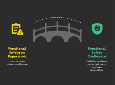
Functional safety is not paperwork; it is data‑driven confidence. Static analysis proves code is tidy; requirements & robustness tests prove behavior; structural coverage proves we looked everywhere. Different industries phrase the rules differently, but the universal spine is shared. Adopt a disciplined, automated testing pipeline that walks the right‑hand leg of the V‑model every day, and you will satisfy auditors, protect end‑users, and free engineers to innovate

1 | Everyday Glitches vs. Catastrophic Failures 

Ever had your smart thermostat overshoot the set-point, your robot vacuum freeze mid-room, or your streaming box reboot during a match? Mild inconvenience—power-cycle and move on. 
Now transpose that glitch to a power-steering ECU, a gas-boiler controller, or an ICU ventilator. One hiccup leaps from nuisance to danger. 

That mental jump is the essence of functional safety—the discipline that keeps critical functions either operating safely or steering into a harmless state when all else fails. 

2 | Why We Invest in Rigorous Testing 

Connected products are now systems-of-systems; one flipped bit or delayed interrupt can injure or kill. International standards—ISO 26262, IEC 61508, IEC 62304, DO-178C, EN 50128—codify the risk-based rules that society accepts as the price of trust. 
Design reviews and FMEAs anticipate faults, but only disciplined, multi-layer testing produces hard evidence that the real code, on real hardware, consistently behaves under worst-case conditions. 

3 | Where Verification Fits—The V-Model at a Glance 

Verification Gate Question Answered Typical Activities Trigger Point 
Code-Quality Gate Does the code obey our engineering rules? Static analysis, MISRA/CERT checks, data-flow reviews Each build & pre-release 
Intended-Behaviour Proof Does the code do what it shouldRequirements-based & timing tests, resource-usage checks Unit → Integration → System 
Unintended-Behaviour Defence Does the code not do what it mustn’t? Boundary analysis, fault-injection, robustness suites Mostly Unit & Integration 
Test-Sufficiency Evidence Have we tested enoughStructural coverage (statement → branch → MC/DC) + traceability Continuous, build report 

Coverage metric is integrity-level specific—e.g., ASIL D / DO-178C Level A demand MC/DC, while IEC 62304 Class B accepts branch coverage. 

4 | Zoom Levels and Their Payoffs 

Test Level Scope FuSa Rationale Real-World Tool Hooks 
Unit Single compilation unit / class / function Catches logic slips early; low-cost path to 100 % MC/DC GoogleTest + Bullseye, CppUMock, Tessent 
Integration Cluster of units exercising real interfaces Exposes timing and resource interactions invisible at unit level Vector CANoe, ETAS LABCAR, custom API shims 
System Deployed binary on target HW/SW stack Validates watchdogs, FTTI, degradation modes end-to-end dSPACE SCALEXIO HIL, NI-PXI fault-injection, Lauterbach 

5 | Cross-Standard Verification Matrix (with Clauses) 

# Test / Verification Method ISO 26262-6 (ASIL D) DO-178C (Lvl A) IEC 62304 (Class C) IEC 61508-3 (SIL 3) EN 50128 (SIL 4) Reference* 
Static code analysis ✓ ✓ ✓ ✓ ✓ 26262-6 §9.4.5(c); DO-178C Tbl A-5 Obj 5; 62304 §5.5.3; 61508-3 Tbl A.12; 50128 Tbl A.4 
Peer code review ◆ ✓ ✓ ✓ ✓ 26262-6 §9.4.5(d); DO-178C §6.3.2; 62304 §5.5.4; 61508-3 Tbl A.13; 50128 §6.3.4 
Requirements-based functional tests ✓ ✓ ✓ ✓ ✓ 26262-6 §10.4.6; DO-178C Tbl A-7 Obj 2; 62304 §5.6; 61508-3 §7.4.4; 50128 §4.2 
Boundary-value analysis ✓ ✓ ◆ ✓ ✓ See above clauses + DO-330 Tbl B-4 for tool qual. 
Fault-injection / error seeding ✓ ◆ ◆ ✓ ✓ 26262-6 §10.4.6(g); DO-178C §6.4.4.1d; 62304 Amd1 Annex C; 61508-3 Tbl A.16; 50128 §6.8 
Timing / WCET tests ✓ ✓ ◆ ✓ ✓ 26262-6 §11.4.5; DO-178C §6.4.4.2; 62304 §5.8; 61508-3 §7.4.12; 50128 §6.7 
Structural coverage ✓ ✓ ✓ ✓ ✓ 26262-6 §9.4.5(f); DO-178C Tbl A-7 Obj 6; 62304 §5.7.5; 61508-3 §7.4.10; 50128 §6.9 

Legend: ✓ = Explicitly required (highest integrity class); ◆ = Highly recommended; — = Not explicitly addressed 
*Clause citations use latest amendments as of June 2025

Key Observations 

  1. Static analysis + requirements-centred testing are non-negotiable everywhere. 
  1. Divergence shows up in robustness and resource/timing tests—mirroring domain-specific hazards. 
  1. “Coverage complete” means complete for the mandated metric—100 % statement beats 90 % MC/DC. 

6 | Automation—Scaling Evidence to 100 % 

Manual testing collapses under: 

Challenge Why Automation Wins 
Regression depth Impact analysis scripts select only the changed-function test set ⇒ minutes, not days. 
MC/DC explosion Vector or Rapita tools auto-synthesise input vectors; human generation is infeasible. 
Traceability payload ALM (Application Lifecycle Management) suites—e.g., Polarion, Codebeamer—consume JSON or REST feeds from test rigs, building real-time audit trails. 

Swift Act’s Reference Loop 

  1. Harness generator emits host-side and target-side stubs per commit. 
  1. Dual execution on GCC/Clang and qualifier compiler (e.g., Green Hills) to catch toolchain quirks. 
  1. Coverage merger uploads .xccovreport & .gcov into ALM; requirement ⇄ test ⇄ code links materialise instantly. 
  1. CI gatekeeper in GitHub Actions / Gerrit blocks merge on any failed lane or coverage dip. 

Result: confirmed in an ASIL C powertrain project—release cadence shrank from 12 → 6 weeks while certification artefact count doubled

Alternative terminology: ALM is also labelled SDLC management suite or PLM test-collaboration module in some organisations. 

7 | Common Pitfalls & How to Dodge Them 

Pitfall Mitigation 
Late-stage coverage chase Enforce coverage thresholds from sprint 1; break the build early. 
Non-deterministic tests Isolate hardware timers, mock randomness, and pin OS scheduling via affinity. 
Unqualified tools Apply ISO 26262-8 tool-classification; qualify per DO-330 if re-used for avionics. 

8 | Conclusion & Next Step 

Functional safety is not paperwork; it is data-driven confidence

  • Static analysis proves code hygiene. 
  • Requirements & robustness tests prove behaviour. 
  • Structural coverage proves we inspected every path. 

Adopt a disciplined, automated verification pipeline that walks the right-hand leg of the V-model every day and you will: 

✔ satisfy auditors ✔ protect end-users ✔ free engineers to innovate 

Ready to cut verification time in half?Book a 30-minute scoping workshop with Swift Act’s FuSa automation team. 

Read More
Blogs FuSa-Blogs

Tool Qualification for Safety Compliance 

Build trust in every step of your workflow. 

Tools Qualification in Compliance with Safety Standards 

The use of software development tools can be greatly beneficial in the development of safety-related electric and/or electronic (E/E) systems. In safety-critical domains such as automotive, aerospace, and medical devices, adherence to safety standards like ISO 26262, DO-178C, and IEC 62304 cannot be neglected. The ability to automate repetitive and time-consuming activities can increase confidence in safety-critical systems by eliminating the possibility of human error during such predictable activities. One key aspect of compliance is ensuring that the tools used in software development are qualified for their intended purpose. 

In this article, we will be looking through the process of integrating some of these tools, namely the static analysis automation tools, into our work environment. Static analysis tools such as Cppcheck and Clang are increasingly favored for their ability to enhance code quality, detect potential bugs, and enforce coding standards. 

The Significance of Tool Qualification 

To minimize the risks associated with tool usage, and to ensure their reliability, functional safety standards emphasize the importance of gaining confidence in the tools used during the development of electronic and electrical systems. In the development of safety-critical automotive software, meeting the tool classification and qualification requirements outlined in ISO 26262 is crucial for ensuring compliance with these safety standards. 

Tool Qualification Process 

Part 8 of the ISO 26262 standard calls for a 2 step qualification process: 

  1. Tool classification 

To determine the tool confidence level (TCL) of the tool under qualification, we first need to analyze and document the actual/intended usage of the tool. Use cases are used for this purpose, and potential tool errors that could occur in the context of the considered use case need to be identified and documented. Then the tool is classified to have a tool impact of 1 (TI1) if there is no possibility that the tool could introduce such errors into the system (or fail to detect such error within the system), or to have a tool impact of 2 (TI2) if that is not the case (meaning the tool could possibly introduce/fail to detect said error). 

Then, an evaluation is done of the measures taken to either prevent or at least detect such errors, and the efficacy is rated based on the confidence level of these measures, having either high (TD1), medium (TD2), or low (TD3) confidence levels. Note that TD1 means there is high confidence that the measures applied to the tool will prevent/detect the tool error under analysis. 

Eventually, we assign a tool confidence level (TCL) based on the following matrix, with TCL1 indicating the highest level of confidence and TCL3 the lowest: 

 Tool Error Detection 
TD1 TD2 TD3 
Tool Impact TI1 TCL1 TCL1 TCL1 
TI2 TCL1 TCL2 TCL3 
  1. Tool qualification 

After classifying the tool to one of the described TCLs, we assess the need for a tool qualification process. Generally, a tool having the confidence level of TCL1 will not require additional actions.  

For TCL2 and TCL3, the ISO 26262 standard calls for a tool qualification process using any or a combination of the following methods: 

(1a) Increased confidence from use 

(1b) Evaluation of the tool development process 

(1c) Validation of the software tool 

(1d) Development in compliance with a safety standard 

Note that ISO26262 highly recommends methods 1a and 1b for projects with all ASIL levels except for ASIL D, with which it is recommended to use methods 1c and 1d for the tool qualification process. 

Project Overview 

The project focused on developing a car Body Control Module (BCM), a critical component in modern automotive systems responsible for managing vehicle functions such as lighting, door locking, and windshield wipers. As the BCM is a safety-related system, the development process needed to adhere to stringent functional safety and coding standards, including ISO 26262 for functional safety, MISRA-C for coding guidelines, and ASPICE for software development process assessment. The development team needed to qualify static analysis tools to meet such compliance requirements. The team selected Cppcheck and Clang tools due to their robust analysis capabilities and support for coding standards such as MISRA-C. 

Implementing Static Analysis Tools 

Why Cppcheck and Clang? 

Cppcheck and Clang were chosen for their complementary capabilities: 

  • Cppcheck: Lightweight, open-source static analysis tool specializing in MISRA-C compliance and customizable checks. 
  • Clang: Advanced analysis capabilities for runtime defect detection and enforcing CERT-C guidelines. 

Both tools offer seamless integration into CI/CD pipelines and support for custom rule definitions. 

Integration Process 

The integration of these tools involved: 

  1. Configuration:  

We customized the tool configurations to meet MISRA-C and project-specific coding rules. We opted to choose configurations that would not alter already existing tools so as to avoid introducing tool-born errors into the system, choosing instead to make any modifications manually after reviewing the result of the static analysis. We also analyzed the pre-existing checks for both tools for homogeneity and consistency, to avoid conflicting results and unnecessary checks. 

  1. Pipeline Automation:  

We integrated the tools into the CI/CD pipeline to automate static analysis checks by creating automated batch scripts to invoke the static analysis activities and analyze the results for confirmation before each build process. This provided control over the level of restrictions enforced by static analysis activities over the different stages of development. 

  1. Baseline Establishment:  

Initial scans identified and documented existing issues, which helped us to create a baseline of the state of each tool, which assisted in further stages of tool analysis and qualification process. 

Validation and Qualification of Tools 

Validation Activities 

Cppcheck and Clang were validated using an open-source python test suite that assessed the tools’ ability to detect a range of known defects. Additionally, we used real-world scenarios from the BCM project as project benchmarks to evaluate tool performance. 

Qualification Activities 

Qualification followed ISO 26262 guidelines: 

  • Increased Confidence from Use: Historical data from similar projects were found to demonstrate tool reliability 
  • Validation of Software Tools: Verification tests using a variety of testing techniques confirmed the tools’ ability to detect specific categories of injected errors. 

Challenges Faced and their Solutions 

  1. False Positives:  

One of the primary challenges was the high volume of false positives generated by the static analysis tools during the initial scans. This led to unnecessary time spent reviewing non-issues, which slowed down the development process and diverted attention from genuine defects. The team carefully fine-tuned the tools’ configurations and rulesets. Custom scripts were developed to filter out warnings unrelated to the project’s coding guidelines.  

  1. Frequent Updates:  

Static analysis tools like Clang and Cppcheck undergo frequent updates to enhance functionality, fix bugs, and add new rules. While beneficial in the long term, new versions introduced unexpected behavior, altered outputs, and flagged additional issues, requiring revalidation and requalification efforts. To mitigate this, a staging environment was set up where tool updates could be rigorously tested before introducing into the development environment. Versioning the static analysis solution while ensuring backward compatibility provided confidence for use in the project. 

  1. Performance Bottlenecks: 

When scanning large codebases, the analysis tools exhibited performance bottlenecks, leading to prolonged execution times. This slowed down the CI/CD pipeline. The team optimized the analysis scope by excluding non-critical files from scans and parallelizing the analysis tasks where possible. Additionally, incremental analysis was employed, focusing only on modified or newly added code. Lastly, tiering the solution to allow for partial runs of the analysis tools proved to be time saving while still maintaining the benefits of using the tools. 

  1. Documentation Overhead:  

ISO 26262 mandates detailed documentation of the tool qualification process. Generating this documentation in a manner that satisfied both internal and external audits was challenging. Without proper documentation, demonstrating compliance during certification audits could be problematic. The team developed templates and checklists to streamline the documentation process. Automated reporting scripts were also created to capture tool outputs and validation results, reducing manual effort and improving traceability. 

Results and Observations 

Impact on Code Quality 

  • Improved Compliance: Adherence to MISRA-C and CERT-C standards. 
  • Defect Reduction: Early detection of potential runtime and logical errors. 

Process Efficiency 

  • Automated checks reduced manual review effort. 
  • CI/CD integration accelerated defect resolution timelines. 

Compliance Benefits 

Tool qualification ensured certification audits readiness, demonstrating compliance with ISO 26262 and ASPICE. 

Conclusion 

Tool qualification is a critical component in safety-critical projects, enabling the reliable development of compliant systems. By integrating and qualifying Cppcheck and Clang, the BCM project achieved enhanced code quality, streamlined workflows, and adherence to stringent safety standards. This case study underscores the importance of a structured approach to tool qualification for delivering reliable and certifiable software. 

Read More
Blogs FuSa-Blogs

Smart tips to align your product with safety standards.  

Safety First. Compliance Always.

Having worked across standards like ISO 26262 (ASIL A–D), IEC 61508 (SIL 3), IEC 62304 (Class A/B), and FDA 510(k)/EUA, I’ve collected five top tips and tricks for developing a safety-compliant product 

1. Tip: Adopt a Safety Mindset from Day Zero 

Safety is not just documentation; it’s about having a certain level of confidence (e.g., ASIL C, SIL 3, Class B) that the product will not fail to meet its safety goals. 
I’ve seen two recurring traps: 

  • Overengineering: Some teams develop their product to reach the highest level of confidence, leading to budget overruns or a product with low performance and poor maintainability. 
  • Procrastination: Postponing the safety topic entirely, which ends up requiring a lot of rework for certification. Sometimes, the rework becomes catastrophic due to a non-compliant system architecture or incompatible hardware targets. 

Trick: At project kickoff, run a gap analysis across People, Process, and Product. 

  • People: Are all stakeholders trained for the required safety level (e.g., ASIL C, SIL 3, Class B)? 
  • Process: Is your development lifecycle aligned with the relevant safety standard? 
  • Product: If your product is reused, what must be done to reach compliance? 

2. Tip: Choose Tools Based on Safety Needs, Not Popularity 

Tool selection should be driven by the specific requirements of your safety activities, not by brand reputation or complexity. A tool is only valuable if it supports the processes needed for compliance with your safety standard (e.g., ISO 26262, IEC 61508, IEC 62304). In some cases, a simple spreadsheet or custom script may be sufficient — high-end tools are not always necessary or justified. 

Trick: At project kickoff, perform a tool impact analysis 

Determine whether tool qualification is required based on the safety standard being followed. 

3. Tip: Safety-Graded Doesn’t Mean Plug-and-Play 

If you purchase a safety-graded hardware or software component, or a Safety Element out of Context (SEooC), it does not mean that no integration effort is required. You must ask the supplier for the safety manual to determine whether the listed constraints can be fulfilled within your project context. In some cases, even a safety-graded component may not be suitable for your use case. For example, an ASIL D operating system may provide a safe execution context but might not ensure correct task monitoring, which could be critical for your system. 

Trick 1: Perform safety analysis activity before purchasing the SEooC. 
During the safety analysis, each component’s undesired event and its impact on the safety goal is determined. Sometimes the system already includes alternative safety mechanisms, making the purchase unnecessary. The safety analysis helps justify whether the buy decision is technically needed or not. 

Trick 2: Consider safety specification activities within your project planning. 
Once a SEooC is selected, it’s important to define corresponding software or hardware safety requirements early in the planning phase. This ensures traceability, helps evaluate supplier deliverables properly, and prevents costly rework late in development. 

4. Tip: Make V&V Reports a Living Part of Your Safety Strategy 

Verification and Validation (V&V) activities are not just checkpoints for compliance — they are essential tools for ensuring that safety requirements are properly addressed throughout development. Treating V&V reports as static documents risks overlooking critical gaps, assumptions, or missed test cases that could compromise safety. 

Trick: Integrate regular V&V report reviews into your project rhythm
By undergoing independent functional safety assessments  for  V&V outputs periodically — not just at major milestones — you maintain continuous alignment with safety goals, improve test traceability, and reduce the likelihood of costly late-stage rework. 

5. Tip: Empower the Functional Safety Manager with Clear Authority and Responsibility 

A weak or symbolic safety role can lead to unclear accountability and fragmented decision-making. The Functional Safety Manager (FSM) must have a clearly defined role with the authority to make safety-related decisions and resolve conflicts across teams. 

Trick: Define and communicate the FSM’s responsibilities early in the project. 
Ensure the FSM is involved in key decisions, safety planning, and audits to avoid gaps in ownership and to maintain safety integrity throughout the development lifecycle. Effective functional safety management helps ensure that the product is confidently released and ready for certification.  

Read More